Architectural Shop Drawings & Details Precision Documentation for Fabrication & Installation
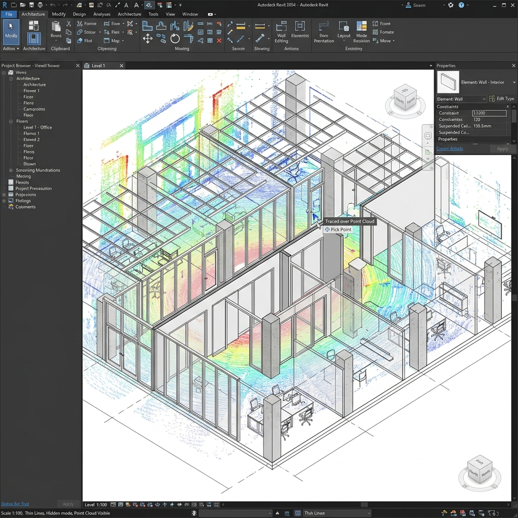
We provide Architectural Shop Drawings and Details that help architects, contractors, and fabricators translate design intent into precise, buildable components. Using Autodesk Revit and advanced BIM workflows, we develop fabrication-ready shop drawings that bridge the gap between design and on-site execution.
Our drawings are developed from detailed 3D Revit models and include comprehensive details for facades, roofs, wall paneling, millwork, stairs, and other architectural elements. We ensure every drawing is accurate, coordinated, and compliant with project specifications.
Construction-Ready Documentation
Architectural shop drawings are detailed, fabrication-ready documents that guide the assembly and installation of building components. They transform the architect's design into precise instructions for fabricators and installers, ensuring that every element is built to specification.
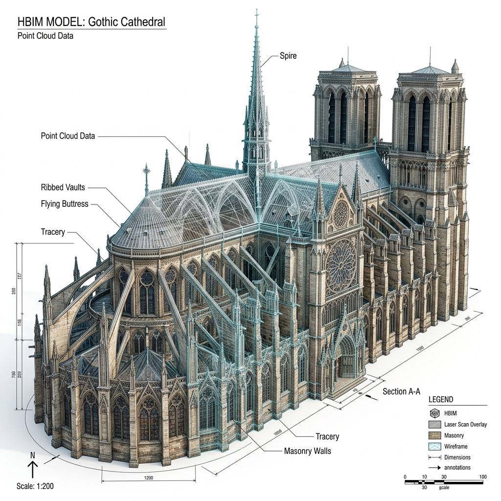
All our shop drawings are generated from LOD 400 models coordinated among trades, including the minutest details pertaining to size, location, shape, and assembly. This level of detail ensures accurate fabrication and smooth on-site assembly.
We deliver:
- 🔴 Floor and roof plans with precise dimensions
- 🔴 Building sections, wall sections, and typical details
- 🔴 Ceiling and soffit details
- 🔴 Door and window schedules with frame profiles
- 🔴 Millwork plans, sections, elevations, and details
- 🔴 Stair plans, sections, and details
- 🔴 Material schedules and specifications
- 🔴 Installation and assembly guides
- 🔴 Fabrication-ready 3D BIM models
Cabinetry Joinery Blueprint Simulator
Select a joinery connection type below to preview panel interlocking mechanics, fastener overlays, and coordinate specifications:
Butt Joint Detail Specs
Our joinery blueprints are coded with exact routing paths and toolpath offsets, facilitating immediate shop floor execution.
- ✓Material thickness compatibility: 12mm - 25mm
- ✓Recommended fastener spacing: 100mm center-to-center
- ✓Requires corner clamping during curing
- ✓Lowest shear resistance, shear keys recommended
Door Frame Profile Extrusion Configurator
Adjust the sliders to dynamically alter the structural aluminum door frame extrusion width and glazing slots:
Coordinated Frame Metadata
Masonry Bond Pattern Selector
Choose a brick alignment standard below to calculate wall structural spacing and load configurations:
Running Bond Layout Logic
Bricks laid in overlapping courses where head joints align with center of bricks below.
Our Architectural Shop Detailing Process
We work systematically through structured drafting, modeling, and coordination reviews to guarantee absolute project accuracy:
Why Architectural Shop Drawings Matter
Avoid field mistakes, eliminate project rework, and optimize material resources with high-fidelity shop layouts.
Fabrication-Ready Accuracy
Architectural shop drawings provide fabricators with precise details needed to manufacture components correctly the first time. They include raw material requirements, dimensions, cutting lengths, and assembly methods, preventing costly waste.
Coordination and Clash Prevention
We ensure proper integration between architectural elements and structural framing, MEP systems, and interior finishes. We run clash detection using Navisworks and resolve conflicts before fabrication starts.
Cost and Time Savings
Accurate details prevent on-site delays, assembly complications, and custom modification costs. Field crews install modular assemblies with absolute certainty of coordinate alignment.
Regulatory Compliance
We incorporate fire safety ratings, local framing tolerances, ADA guidelines, and structural loading calculations directly into the details, ensuring clean building compliance checks.
Related Shop Drawings & BIM Services
Explore sibling services inside the Shop Drawings & Details pillar to support your full package needs:
Frequently Asked Questions
Find technical answers regarding our drafting specifications, deliverables, and trade coordination processes below:
Architectural design drawings show general layout, dimensions, and aesthetic intent for bidding and approvals. Shop drawings are highly detailed, fabrication-ready documents containing precise material specifications, dimensions, offsets, joint configurations, and fastening methods tailored for the fabricator and installer.
We import all architectural drawings, structural grids, and MEP piping/ductwork plans into a unified environment. We run clash detection audits using Navisworks to identify and resolve interference points (such as anchors hitting structural rebar or duct sleeves conflicting with studs) prior to publishing sheets.
Yes. We deliver fabrication-ready millwork drawings including cabinetry layout, casework elevations, detail sections, edge banding details, and cabinetry joinery specifications (such as dowel spacing or dado grooves) for both wood and metal components.
Our architectural shop drawings are developed from Level of Detail (LOD) 400 models. This means the model contains elements with exact size, shape, location, assembly detailing, and fabrication specifications suitable for direct manufacturing.
Our primary software suite includes Autodesk Revit for parametric modeling and extraction, AutoCAD for 2D drafting, and Navisworks Manage for advanced coordination and clash audits.
Yes, we extract exact Bills of Materials, quantity takeoffs, and hardware schedules directly from coordinated 3D models. This eliminates manual takeoff errors and speeds up procurement.
We coordinate with your project team to integrate local zoning regulations, fire safety codes, ADA guidelines, and regional material assembly standards. Every drawing sheet undergoes a detailed check by our QA team.
The turnaround time depends on the project scope and complexity. We prepare a detailed work breakdown structure and timeline during the initial scoping stage. We prioritize fast, high-quality delivery to keep construction on schedule.